Fully controlling modules can regulate and automatically control the voltage of electric power, which have inner automatic regulating circuits, thyristor and phase-shift triggering circuits.
Modules can be widely used in adjusting power, AC and DC current stabilzer, AC motor soft starting, DC motor adjusting speed, industrial heater and temperature control , industrial electrical automations, solid-state switches, various electrical equipments and various power supplies(such as stabilized voltage, electroplate, temperature control, excitation, light control and so on.)
1. Advanced technics and high quality
Using DCB(Direct Copper Bonded Ceramic Substrates) technics and import high performance chips and it makes the modules have long life time and up to 10,000 times of thermal cycling loader.
2. Easy and safe opeation
(1) Using 0-10V(or 0-12V) DC signal can regulate the output voltage and current smoothly.
(2) Easily controlled by hand, instrument or microprocessor.
(3) Triggering circuit systems and thyristors and thermal conductive bagaplates are isolated each other and the insulated strength is greater than 2500V.
(4) No limited for phase series in AC input of 3-phase modules.
(5) Suitable for resistance load
Specifications and types of common constant current modules, see table 1 and table 2.
Table 1
|
name |
type |
specification |
|
3-phase rectifier modules |
MZKS-ZL-2400 |
2400A 450V |
|
MZKS-ZL-1800 |
1800A 450V |
|
|
MZKS-ZL-1200 |
1200A 450V |
|
|
MZKS-ZL-800 |
800A 450V |
|
|
MZKS-ZL-600 |
600A 450V |
|
|
MZKS-ZL-400 |
400A 450V |
|
|
MZKS-ZL-200 |
200A 450V |
|
|
MZKS-ZL-100 |
100A 450V |
|
|
MZKS-ZL-50 |
50A 450V |
|
|
MZKS-ZL-25 |
25A 450V |
|
|
3-phase AC modules |
MZKS-JL-1800 |
3×1800A 450V |
|
MZKS-JL-1350 |
3×1350A 450V |
|
|
MZKS-JL-900 |
3×900A 450v |
|
|
MZKS-JL-600 |
3×600A 450V |
|
|
MZKS-JL-450 |
3×450A 450V |
|
|
MZKS-JL-300 |
3×300A 450V |
|
|
MZKS-JL-150 |
3×150A 450V |
|
|
MZKS-JL-75 |
3×75A 450V |
|
|
MZKS-JL-40 |
3×40A 450V |
|
|
MZKS-JL-20 |
3×20A 450V |
Table 2
|
name |
type |
specification |
|
single-phase rectifier modules |
MZKD-ZL-2400 |
2400A 450V |
|
MZKD-ZL-1800 |
1800A 450V |
|
|
MZKD-ZL-1200 |
1200A 450V |
|
|
MZKD-ZL-800 |
800A 450V |
|
|
MZKD-ZL-600 |
600A 450V |
|
|
MZKD-ZL-400 |
400A 450V |
|
|
MZKD-ZL-200 |
200A 450V |
|
|
MZKD-ZL-100 |
100A 450V |
|
|
MZKD-ZL-50 |
50A 450V |
|
|
MZKD-ZL-25 |
25A 450V |
|
|
single-phase AC modules |
MZKD-JL-1800 |
1800A 4500V |
|
MZKD-JL-1350 |
1350A 450V |
|
|
MZKD-JL-900 |
900A 450V |
|
|
MZKD-JL-600 |
600A 450V |
|
|
MZKD-JL-450 |
450A 450V |
|
|
MZKD-JL-300 |
300A 450V |
|
|
MZKD-JL-150 |
150A 450V |
|
|
MZKD-JL-75 |
75A 450V |
|
|
MZKD-JL-40 |
40A 450V |
Note:
1、In specification volume, the current is the maximal DC average current or AC virtual current. The voltage is the maximal input virtual line voltage.
2、All modules listed are fully controlling modules.
(1) Operating frequency: 50HZ
(2) Input line voltage Vin(RMS) range: 30-450V(AC)
(3) Control voltage VCON range: 0-10V(DC)
(4) Control current: ≤10μA
(5) Unbalanced degree of output voltage: <6%
(6) Temperature coefficient of output voltage: <600PPM/℃
(7) Insulation voltage VISO(RMS): >2500V
About other parameters, see table 3 and table 4.
Table 3
|
Type |
Output Voltage |
Maximal Input Current per phase |
Maximal Output Current |
Triggering Current |
Working Surface Temperature |
|
|
VOU(AV)or VOUT(RMS) |
IIN(RMS) |
IOUT(AV) or IOUT(RMS) |
IE |
Tc |
||
|
V |
A |
A |
mA |
℃ |
||
|
3-phase rectifier modules |
MZKS-ZL-2400 |
1.35VIN |
1800 |
2400 |
400 |
≤80 |
|
MZKS-ZL-1800 |
1440 |
1800 |
400 |
≤80 |
||
|
MZKS-ZL-1200 |
960 |
1200 |
400 |
≤80 |
||
|
MZKS-ZL-800 |
600 |
800 |
400 |
≤80 |
||
|
MZKS-ZL-600 |
480 |
600 |
400 |
≤80 |
||
|
MZKS-ZL-400 |
320 |
400 |
400 |
≤80 |
||
|
MZKS-ZL-200 |
160 |
200 |
400 |
≤80 |
||
|
MZKS-ZL-100 |
80 |
100 |
400 |
≤85 |
||
|
MZKS-ZL-50 |
40 |
50 |
400 |
≤88 |
||
|
3-phase AC modules |
MZKS-JI-1800 |
1.0VIN |
1800 |
3×1800 |
400 |
≤80 |
|
MZKS-JI-1350 |
1350 |
3×1350 |
400 |
≤80 |
||
|
MZKS-JI-900 |
900 |
3×900 |
400 |
≤80 |
||
|
MZKS-JI-600 |
600 |
3×600 |
400 |
≤80 |
||
|
MZKS-JI-450 |
450 |
3×450 |
400 |
≤80 |
||
|
MZKS-JI-300 |
300 |
3×300 |
400 |
≤80 |
||
|
MZKS-JI-150 |
150 |
3×150 |
400 |
≤85 |
||
|
MZKS-JI-75 |
75 |
3×75 |
400 |
≤85 |
||
|
MZKS-JI-40 |
40 |
3×40 |
400 |
≤88 |
||
Table 4
|
Type |
Output Voltage |
Maximal Input Current per phase |
Maximal Output Current |
Triggering Current |
Working Surface Temperature |
|
|
VOUT(AV) or VOUT(RMS) |
IIN(RMS) |
IOUT(AV) or IOUT(RMS) |
IE |
Tc |
||
|
V |
A |
A |
mA |
℃ |
||
|
single- phase rectifier modules |
MZKD-ZL-2400 |
0.9VIN
|
2666 |
2400 |
400 |
≤80 |
|
MZKD-ZL-1800 |
2000 |
1800 |
400 |
≤80 |
||
|
MZKD-ZL-1200 |
1333 |
1200 |
400 |
≤80 |
||
|
MZKD-ZL-800 |
888 |
800 |
400 |
≤80 |
||
|
MZKD-ZL-600 |
666 |
600 |
400 |
≤80 |
||
|
MZKD-ZL-400 |
444 |
400 |
300 |
≤80 |
||
|
MZKD-ZL-200 |
222 |
200 |
300 |
≤80 |
||
|
MZKD-ZL-100 |
111 |
100 |
300 |
≤85 |
||
|
MZKD-ZL-50 |
55 |
50 |
300 |
≤85 |
||
|
single- phase AC modules
|
MZKD-JL-1800 |
1.0VIN |
1800 |
1800 |
400 |
≤80 |
|
MZKD-JL-1350 |
1350 |
1350 |
400 |
≤80 |
||
|
MZKD-JL-900 |
900 |
900 |
400 |
≤80 |
||
|
MZKD-JL-600 |
600 |
600 |
400 |
≤80 |
||
|
MZKD-JL-450 |
450 |
450 |
300 |
≤80 |
||
|
MZKD-JL-300 |
300 |
300 |
300 |
≤80 |
||
|
MZKD-JL-150 |
150 |
150 |
200 |
≤80 |
||
|
MZKD-JL-75 |
75 |
75 |
200 |
≤85 |
||
|
MZKD-JL-40 |
40 |
40 |
200 |
≤88 |
||
Table 5
|
Module type
|
IT(AV) |
VRRM VDRM |
ITSM |
IRRM IDRM |
RJC |
TJ |
di/dt |
dv/dt |
|
TC= 85℃ |
T= 125℃ |
45℃10ms |
125℃ |
max |
max |
. |
. |
|
|
A |
V |
A |
mA |
℃/W |
℃ |
A/μs |
V/μs |
|
|
MZKS-ZL-800 |
320 |
1200~2200 |
8000 |
20 |
0.04 |
125 |
100 |
500 |
|
MZKS-ZL-600 |
||||||||
|
MZKS-JL-600 |
||||||||
|
MZKS-JL-450 |
||||||||
|
MZKS-ZL-400 |
250 |
6400 |
15 |
0.05 |
||||
|
MZKS-JL-300 |
||||||||
|
MZKS-ZL-200 |
110 |
2200 |
10 |
0.15 |
||||
|
MZKS-JL-150 |
||||||||
|
MZKD-ZL-800 |
320 |
8000 |
20 |
0.04 |
||||
|
MZKD-ZL-600 |
||||||||
|
MZKD-JL-600 |
||||||||
|
MZKD-JL-450 |
||||||||
|
MZKD-ZL-400 |
200 |
5000 |
15 |
0.07 |
||||
|
MZKD-JL-350 |
||||||||
|
MZKD-ZL-200 |
100 |
1800 |
10 |
0.15 |
||||
|
MZKD-JL-150 |
||||||||
|
MZKS-ZL-100 |
50 |
1200~1800 |
1100 |
10 |
0.03 |
|||
|
MZKS-JL-75 |
0.04 |
|||||||
|
MZKD-ZL-100 |
||||||||
|
MZKD-JL-75 |
[
词汇翻译:
输出: Output
输入: Input
移相调控器:Phase-shift controller
]
(1)single-phase rectifier modules
|
|
(2) single-phase AC modules
|
|
(3)3-phase rectifier modules
|
|
(4)3-phase AC modules
|
|
See figure 5 – figure 8.

Fig.5 single-phase rectifier modules Fig.6 single-phase AC modules

Fig.7 3-phase rectifier modules Fig.8 3-phase rectifier modules
The load performance of output curve is like that of a resistor in this chart. The chart is only a reference for customers.
[
词汇翻译:
输出: output
输入: input
三相整流:3-phase rectifier
三相交流:3-phase AC
单相整流:single-phase rectifier
控制:control
]
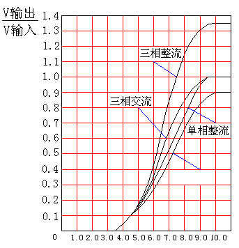
Fig.9 fully controlling module
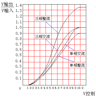
Fig.10 half controlling module
(1).Modules type selection:
Current of choosed modules should be 1.5~3 times than current of load in order to make equipments safely work.. Current of load shouldn’t be greater than rated current of modules during the working process.
(2). Environment required:
Modules must be worked or stored in places that are dried, ventilated, dusty-less and have no corrosive gases. Atmosphere temperature required varies from -25℃ to +45℃.
(3) .Installation steps
① Install radiators and wind machines in order to accord with cooling requirement. The surface of radiators must be plat and clean. A layer of thermal conductive silica gel must be laid equably between the module thermal conductive bagaplates and the surface of radiators. Then screw modules on radiators with equal strength.
② Mutliple section copper wires must be used to connect with modules because of their large current. Aluminium wires are prohibited. Wire section is selected according to current density(<4A/mm2).Must’t connect copper wires with module poles directly.
③ Tie up copper wires with junction nose rings for fear of additional quantity of heat caused by bad connection, then place insulative pyrocondensation cannula on wires and make them shrink with hot wind or water. Screw junction noses in module poles and make them connected well in their surface.
④ Don’t lift up poles for fear of breaking off poles.
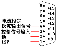
⑤ Two types are applied for control port: one has five pins, the other has fifteen pins.About specification , see table 6 and figure 11-12.
[
词汇翻译:
输出: Output 输入: Input
电流设定: Initialization current
稳流输出信号:Constant current signal output
控制信号输入: Control signal input
 地:GND
地:GND
]
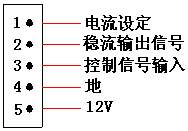
Fig.11 five-pin socket specification Fig.12 fifteen-pin socket Specification
Table 6
|
pin function |
color |
five-pin socket |
fifteen-pin socket |
|
+12V |
red |
5 |
1 |
|
GND |
black |
4 |
2 |
|
control signal input |
black(gray) |
3 |
3 |
|
constant current signal output |
yellow |
2 |
4 |
|
initialization current |
orange |
1 |
5 |
Hand control(using resistors)interface, computer control interface and instrument control interface, see figure 11-13.
[
翻译说明
计算机D/A输出(0-10V): computer D/A output (0-10V)
]
|
|
Fig.13 hand control interface Fig.14 computer control interface
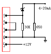
Fig.15 instrument control interface(regulator diode: 2.4v- 2.7v)
|
|
Fig.16 inteface with 0-5vsignal
Orange pin connects to 10.5V DC power supply in modules. Red pin connects to anode of 12V DC stable power supply which output current value is greater than 1A. The power of transformer should be greater than 15W and it has better that two filter capacitor(2200μF/25V) is shunt-wound if a transformer rectifier stable power supply is adopted. Pay attention not to connect reversely, otherwise it will destroy modules.
It should be attended that a load must be connected to output pin and the minimum output current value is greater than 10 mA when we measure output voltage. It is not accurate when no load is connected. If we measure output voltage with a multi-meter, please take read pin and black pin of multi-meter on phase in AB,BC,CA order, otherwise the voltage value we get is not accurate.
1.Over-current protection
The simplest protection method is to connect quick fuses outside of modules. Only a brief introduction is given as follows.
(1) Connection
Quick fuses are connected in AC input sides. A example is given to 3-phase rectifier modules and single-phase AC modules.See figure 15 and figure 16.
[
翻译说明
[输出: Output
|
|
输入: Input
]
Fig.17 3-phase rectifier modules Fig.18 single-phase AC modules
(2) selection of quick fuses
①The rated voltage of selected quick fuses must be greater than that of working voltage in circuits
②About rated current selection of fuses, see table 7 and table 8.
Table 7
|
module type(3-phase) |
fuse |
|||
|
rated voltage(~V) |
rated current(A) |
quantity |
||
|
MZKS-ZL-2400 |
500 |
1200 |
3 |
|
|
MZKS-JL-1800 |
||||
|
MZKS-ZL-1800 |
900 |
3 |
||
|
MZKS-JL-1350 |
||||
|
MZKS-ZL-1200 |
480 |
3 |
||
|
MZKS-JL-900 |
||||
|
MZKS-ZL-800 |
400 |
3 |
||
|
MZKS-JL-600 |
||||
|
MZKS-ZL-600 |
300 |
3 |
||
|
MZKS-JL-450 |
||||
|
MZKS-ZL-400 |
160 |
3 |
||
|
MZKS-JL-300 |
||||
|
MZKS-ZL-200 |
80 |
3 |
||
|
MZKS-JL-150 |
||||
|
MZKS-ZL-100 |
40 |
3 |
||
|
MZKS-JL-75 |
||||
|
MZKS-ZL-50 |
25 |
3 |
||
|
MZKS-JL-40 |
||||
|
MZKS-ZL-25 |
||||
|
16 |
3 |
|||
|
MZKS-JL-20 |
||||
Table 8
|
module type(single-phase) |
fuse |
||
|
rated voltage(~V) |
rated current(A) |
quantity |
|
|
MZKD-ZL-2400 |
500 |
960 |
1 |
|
MZKD-JL-1800 |
|||
|
MZKD-ZL-1800 |
720 |
1 |
|
|
MZKD-JL-1350 |
|||
|
MZKD-ZL-1200 |
480 |
1 |
|
|
MZKD-JL-900 |
|||
|
MZKD-ZL-800 |
320 |
1 |
|
|
MZKD-JL-600 |
|||
|
MZKD-ZL-600 |
240 |
1 |
|
|
MZKD-JL-450 |
|||
|
MZKD-ZL-400 |
160 |
1 |
|
|
MZKD-JL-300 |
|||
|
MZKD-ZL-200 |
80 |
1 |
|
|
MZKD-JL-150 |
|||
|
MZKD-ZL-100 |
40 |
1 |
|
|
MZKD-JL-75 |
|||
|
MZKD-ZL-50 |
25 |
1 |
|
|
MZKD-JL-40 |
|||
|
MZKD-ZL-25 |
|||
2、Over-voltage protection
Resistor-capacitor absord and press-sensitive resistor method is recommended to used together in order to realize over-voltage protection.
(1) Resistor-capacitor absord circuits
Capacitors absorb electromagnetic energy of over-voltage and store to electrostatic energy. Resistors prevent resonance of capacitors and inductances. This absord circuits can restrain over-voltage produced by thyristors when they vary form connection to shutoff and effectively avoid breaking down of modules. About electrical circuits, see figure 19-22. About the value of resistors and capacitors, see table 9-10.
[
翻译说明
[输出: Output
输入: Input
]
。
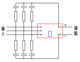
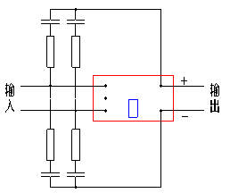
Fig.19 3-phase rectifier modules Fig.20 single-phase rectifier modules
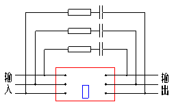
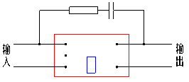
Fig.21 3-phase AC modules Fig.22 single-phase AC modules
Table 9
|
name |
module type |
R(Ω/W) |
C(μF)630VAC |
quantity |
|
3-phase rectifier modules |
MZKS-ZL-2400 |
4/20 |
0.68 |
each 18 |
|
MZKS-ZL-1800 |
||||
|
MZKS-ZL-1200 |
||||
|
MZKS-ZL-800 |
each 6 |
|||
|
MZKS-ZL-600 |
||||
|
MZKS-ZL-400 |
||||
|
MZKS-ZL-200 |
8/10 |
0.32 |
each 6 |
|
|
MZKS-ZL-100 |
30/6 |
0.22 |
each 6 |
|
|
MZKS-ZL-50 |
60/3 |
0.22 |
each 6 |
|
|
MZKS-ZL-25 |
||||
|
3-phase AC modules |
MZKS-JL-1800 |
4/20 |
0.68 |
each 9 |
|
MZKS-JL-1350 |
||||
|
MZKS-JL-900 |
||||
|
MZKS-JL-600 |
each 3 |
|||
|
MZKS-JL-450 |
||||
|
MZKS-JL-300 |
||||
|
MZKS-JL-150 |
8/10 |
0.32 |
each 3 |
|
|
MZKS-JL-75 |
30/6 |
0.22 |
each 3 |
|
|
MZKS-JL-40 |
60/3 |
0.22 |
each 3 |
|
|
MZKS-JL-20 |
Table 10
|
name |
module type |
R(Ω/W) |
C(μF)630AC |
quantity |
|
single-phase rectifier modules |
MZKD-ZL-2400 |
4/20 |
0.68 |
each 12 |
|
MZKD-ZL-1800 |
||||
|
MZKD-ZL-1200 |
||||
|
MZKD-ZL-800 |
each 4 |
|||
|
MZKD-ZL-600 |
||||
|
MZKD-ZL-400 |
||||
|
MZKD-ZL-200 |
8/10 |
0.32 |
each 4 |
|
|
MZKD-ZL-100 |
30/6 |
0.22 |
each 4 |
|
|
MZKD-ZL-50 |
60/3 |
0.22 |
each 4 |
|
|
MZKD-ZL-25 |
||||
|
single-phase AC modules |
MZKD-JL-1800 |
4/20 |
0.68 |
each 3 |
|
MZKD-JL-1350 |
||||
|
MZKD-JL-900 |
||||
|
MZKD-JL-600 |
each 1 |
|||
|
MZKD-JL-450 |
||||
|
MZKD-JL-300 |
||||
|
MZKD-JL-150 |
8/10 |
0.32 |
each 1 |
|
|
MZKD-JL-75 |
30/6 |
0.22 |
each 1 |
|
|
MZKD-JL-40 |
60/3 |
0.22 |
each 1 |
(2)压敏电阻吸收回路
压敏电阻吸收由于雷击等原因产生的能量较大、持续时间较长的过电压。压敏电阻电压选取:710V≤V1mA≤1000V。V1mA是压敏电阻标称电压,是指压敏电阻流过1mA电流时它两端的电压。接线方法见图23-图24:
(2) Press-sensitive resistor absord circuits
Press-sensitive resistors can absorb over-voltage which have more energy and last more time produced by thunder. The voltage value should be: 710V≤V1mA≤1000V。V1mA is rated voltage of press-sensitive resistors. That is the voltage value in resistors when 1mA current flows. About electrical circuits, see figure 23-24.
[
翻译说明
[输出: Output
输入: Input
]
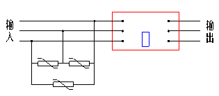
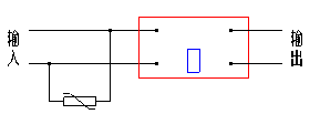
Fig.23 3-phase circuits Fig.24 single-phase circuits
3. Selection of radiators
Radiators must be used during modules work because modules will produce much heat caused by the voltage difference in modules. Reliability and safety are directly depended on conditions of heat emanating.
Generally, there are three ways of heat emanating: water-cooling, forced wind-cooling and natural cooling. In the first place water-cooling is choosed for it’s good cooling effectivity if we can use. Forced wind-cooling is the commonest way used to emanate heat ,but wind velocity of axis stream wind machines must be great than 6m/s. Natural cooling is seldom used because of its bad cooling effectivity and large cubage. We must make air convect better surround radiators if natural cooling is used.
We list types and length of radiators that required by different types of modules when modules work in condition of rated current and 40℃ atmosphere temperature so that a reference is given for customers. The length of radiator may reduce if modules work below full-load.
Table 11 list of radiators
|
Module type |
Radiator type |
Rediator length(mm) |
Axis stream wind machine |
|
|
Forced wind-cooling |
Natural cooling |
|||
|
MZKS-ZL--2400 |
DXC-573 |
1800 |
. |
AC220V/50Hz/ 100W quantity:3 |
|
MZKS-JL--1800 |
||||
|
MZKS-ZL--1800 |
1200 |
. |
||
|
MZKS-JL--1350 |
||||
|
MZKS-ZL--1200 |
900 |
. |
AC220V/50Hz/44W 220×220×60 quantity:3 |
|
|
MZKS-JL--900 |
||||
|
MZKD-ZL--2400 |
||||
|
MZKD-JL--1800 |
||||
|
MZKD-ZL--1800 |
780 |
. |
||
|
MZKD-JL--1350 |
||||
|
MZKD-ZL--1200 |
||||
|
MZKD-JL--900 |
||||
Table 12
|
Module type |
Radiator type |
Rediator length(mm) |
Axis stream wind machine |
|
|
Forced wind-cooling |
Natural cooling |
|||
|
MZKS-ZL--800 |
DXC-573 |
1800 |
. |
AC220V/50Hz/100W |
|
MZKS-JL--600 |
||||
|
MZKS-ZL--600 |
1200 |
. |
||
|
MZKS-JL--450 |
||||
|
MZKS-ZL--400 |
300 |
. |
AC220V/50Hz/44W 220×220×60 |
|
|
MZKS-JL--300 |
||||
|
MZKD-ZL--800 |
||||
|
MZKD-JL--600 |
||||
|
MZKD-ZL--600 |
260 |
. |
||
|
MZKD-JL--450 |
||||
|
MZKS-ZL--200 |
DXC-578 |
300 |
. |
AC220V/50Hz/38W 172×150×51 |
|
MZKS-JL--150 |
||||
|
MZKD-ZL--400 |
||||
|
MZKS-ZL--100 |
200 |
. |
||
|
MZKS-JL--75 |
||||
|
MZKD-JL--300 |
||||
|
MZKD-ZL--200 |
||||
|
MZKS-JL--40 |
160 |
. |
AC220V/50Hz/10W 120×120×38 |
|
|
MZKS-ZL--50 |
||||
|
MZKD-ZL--100 |
||||
|
MZKD-JL--150 |
||||
|
MZKS-ZL--25 |
. |
120 |
. |
|
|
MZKS-JL--20 |
. |
. |
||
|
MZKD-JL--75 |
. |
. |
||
|
MZKD-ZL--50 |
. |
. |
||
|
MZKD-ZL--25 |
. |
. |
||
|
MZKD-JL--40 |
DXC-721 |
. |
80 |
. |
|
MZKD-JL--20 |
. |
. |
||
About shape and dimension of radiators, see figure 25-26.
|
|
Fig.25 DXC-578
|
|
Fig.26 DXC-573
1.Modules are prohibited to work with large current with a small lead angle(high input, low output). If we do so it will make modules produce more heat and maybe destroy modules. It is recommended that modules work with large current in the condition of a large lead angle(greater than 50 percent of regulated angle).
2. The temperature of modules(measurement points are in the surfaces of radiators which contact with bagaplates of modules tightly and are near the center of modules)should be less than 70℃ when modules work in a stable thermal status, otherwise it will destroy modules.
3.Don’t use modules to isolate electric network and people bodies. Air switchs should be installed before modules to ensure people’s safety.
4. Take and lay modules lightly to avoid strong knock and shock when modules are transferred and installed.
5. The content of charts and tables in this specification is only a reference for customers. Apologize for not inform customers if parameters change.